Data and power cables
The storage system supports a variety of data and power cables for specific hosting environments.
Required cables
The quantities and lengths of the cables required for storage system installation vary according to the specific storage system and network configuration. Fibre Channel and iSCSI cables are used to connect the controllers to a switch or host. Serial-attached SCSI (SAS) cables are used to connect drive trays to controllers and other drive trays.
The following table describes the cables required to perform storage system connections at the time of installation.
|
Interface type |
Connector type |
Cable requirements |
|
Fibre Channel |
LC-LC |
Use a Fibre Channel cable to connect the Fibre Channel ports on each controller to a host computer (direct connection), or to or several host computers via a Fibre Channel switch. See the note and table below. |
|
iSCSI (optical) |
LC-LC |
Use an optical Ethernet cable to connect the iSCSI 10 Gb SFP ports on each controller to a host computer (direct connection), or to several host computers via an Ethernet switch. |
|
iSCSI (copper) |
RJ-45 |
Use a shielded Category 5e or 6a Ethernet cable to connect the iSCSI 10 Gb RJ-45 ports on each controller to a host computer (direct connection), or to several host computers via an Ethernet switch. |
|
SAS |
SAS optical |
Connects the controller to a drive tray or a drive tray to another drive tray. Two SAS cables are provided with each drive tray. SAS cables are also used to connect NAS modules to switches. |
|
Ethernet |
RJ-45 |
Four shielded Category 5e or 6a Ethernet cables are required for connecting the SVP to the controllers, management console PC, and network switch. |
|
Cable size |
Speed |
Maximum cable length |
|
9 micron |
1 Gbps |
1 km (3281 ft) |
|
2 Gbps |
2 km (6562 ft) | |
|
50 micron |
2 Gbps |
300 m (984.2 ft) |
|
4 Gbps |
150 m (492.1 ft) | |
|
8 Gbps |
50 m (164 ft) | |
|
16 Gbps |
35 m (115 ft) | |
|
62.5 micron |
2 Gbps |
100 m (328.1 ft) |
|
4 Gbps |
70 m (230 ft) | |
|
8 Gbps |
21 m (69 ft) |
Fibre Channel cables
The storage system supports Fiber Channel connections to hosts. For details about configuring FC host connections, see the Provisioning Guide.
The following figure shows FC direct connection and FC connection through a switch.

The following table lists the data transfer rates and provides the maximum cable lengths.
|
Data transfer rate |
Maximum length of cable | |||
|
Multimode cable |
Single mode cable | |||
|
OM2 |
OM3 |
OM4 | ||
| 2 Gbps | 984.25 ft (300 m) | 1640.4 ft (500 m) | — | 3280.8 ft (10 km) |
| 4 Gbps | 493 ft (150 m) | 1246.72 ft (380 m) | 1312.3 ft (400 m) | |
| 8 Gbps | 164.04 ft (50 m) | 493 ft (150 m) | 623.36 ft (190 m) | |
| 16 Gbps | 114.8 ft (35 m) | 328.08 ft (100 m) | 410.1 ft (125 m) | — |
| 32 Gbps | 65.62 ft (20 m) | 229.7 ft (70 m) | 328.08 ft (100 m) | — |
The following table lists specifications of the Fibre Channel interface cable.
|
Cable type |
Interface |
Cable mode name |
Nominal | ||
|
Cable |
Connector | ||||
|
One side |
Other side | ||||
| LC-LC cable (shortwave) | Optical | Equivalent to DXLC-2P-PC-xxM-GC50, 125-2SR (OMx) | 50, 125 μm, 62.5, 125 μm Multimode
Wavelength: 850 nm | LC connector | LC connector |
|
LC-LC cable (longwave) | DXLC-2PS-SPC-xxM-SMC 10/125-2SR | 9/125 μm Singlemode
Wavelength: 1300 nm | |||
The following figure shows the connector used for optical interfaces.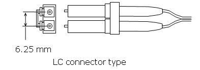
The following figure shows the type of optical connector that connects the storage system Fibre Channel ports.
- LC connector type
- Connector type LC duplex receptacle connector
- Interval 6.25 mm flat type, two rows

iSCSI cables
The storage system supports iSCSI connections to hosts. For details about configuring iSCSI host connections, see the Provisioning Guide.
Cable specifications for iSCSI optical interface
|
Cable type |
Interface |
Cable mode name |
Nominal | ||
|
Cable |
Connector | ||||
|
One side |
Other side | ||||
| LC-LC cable | Optical | Equivalent to DXLC-2P-PC-xxM-GC50, 125-2SR (OMx) |
50, 125 mm Multimode Wavelength: 850 nm | LC connector | LC connector |
The following figure shows the connector used for optical interfaces.
The following figure shows the type of optical connector that connects the storage system optical iSCSI ports.
- LC connector type
- Connector type LC duplex receptacle connector
- Interval 6.25 mm flat type, two rows
Cable specifications for 10 Gbps iSCSI copper interface
|
Cable type |
Maximum cable connection length |
Data transfer |
Transmission band |
Cable |
Connector |
|
Category 5e or 6a LAN cable |
100 m |
1 Gbps |
1000BASE-T |
STP ( use an STP cable that suppresses radio noise) |
RJ-45 |
|
Category 6a LAN cable |
50 m |
10 Gbps |
10GBASE-T |
STP ( use an STP cable that suppresses radio noise) |
RJ-45 |

iSCSI standards
The following standards apply to the management, maintenance, and iSCSI data ports. To configure this system, use switches that comply with the following standards:
- IEEE 802.1D STP
- IEEE 802.1w RSTP
- IEEE 802.3 CSMA/CD
- IEEE 802.3u Fast Ethernet
- IEEE 802.3z 1000 BASE-X
- IEEE 802.1Q Virtual LANs
- IEEE 802.3ae 10 Gigabit Ethernet
- RFC 768 UDP
- RFC 783 TFTP
- RFC 791 IP
- RFC 793 TCP
- RFC 1157 SNMP v1
- RFC 1231 MIB II
- RFC 1757 RMON
- RFC 1901 SNMPv2
iSCSI specifications
|
Item |
Specification |
Comments |
| iSCSI target function | Supported | N/A |
| iSCSI target function | Supported | TrueCopy® only |
| iSCSI ports | 2 per interface board |
VSP Gx00 models: Maximum 32 per iSCSI system |
| Connection methods | Direct and switch connections | |
| Host connections | 255 (maximum per iSCSI port) | With Linux software initiator, the maximum number decreases. |
| Path failover | HDLM1 | Supports Microsoft MPIO (Multi Path I/O) |
| Link | 10 Gbps SFP+ | N/A |
| Transfer speed | 10 Gbps | N/A |
| Connector type | LC | N/A |
| Cable | Optical OM3, OM2 MMF cable | N/A |
| Network switch | L2 or L3 switch | Should comply with IEEE802.3ae |
| Switch cascading | Maximum: 5 switches or fewer | Minimum number of cascading switches is recommended. |
| MAC address | Per port (fixed value) | Factory setting: World Wide Unique value. Cannot be changed. |
| Maximum transfer unit (MTU) | 1,500, 4,500, 9,000 bytes (Ethernet frame) | Jumbo frame, MTU size greater than 1500 |
| Link aggregation | Not supported | N/A |
| Tagged VLAN | Supported | N/A |
| IPv4 | Supported | N/A |
| IPv6 | Supported |
Note the following precautions:
|
| Subnet mask | Supported | N/A |
| Gateway address | Supported | N/A |
| DHCP | N/A | N/A |
| DNS | N/A | N/A |
| Ping (ICMP ECHO) Transmit, Receive | Supported | N/A |
| IPsec2 | N/A | N/A |
| TCP port number | 3260 | Changeable among 1 to 65,535. Observe the following if changing values:
|
| iSCSI name | Both iqn3 and eui4 types are supported | The unique iqn value is automatically set when a target is made. iSCSI name is configurable. |
| Error recovery level | 0 (zero) | Error recovery by retrying from host. Does not support Level 1 and Level 2. |
| Header digest | Supported | Detects header error or data error with iSCSI communication. The storage system follows the host's digest setting. If digest is enabled, the performance degrades. The amount of the degradation depends on factors such as host performance of host and transaction pattern. |
| Data digest | Supported | |
| Maximum iSCSI connections at one time | 255 per iSCSI port | N/A |
| CHAP | Supported | Authentication: login request is sent properly from host to storage. CHAP is not supported during discovery session. |
| Mutual (2-way) CHAP | Supported (not available if connected to Linux software initiator) | Authentication: login request is sent properly from host to storage. |
| CHAP user registration | Max 512 users per iSCSI port | N/A |
| iSNS | Supported | With iSNS (name service), a host can discover a target without knowing the target's IP address. |
|
Note:
| ||
Managing cables
Organize cables to protect the integrity of your connections and allow proper airflow around your storage system.
Never bend cables beyond their recommended bend radius. The following table provides general guidelines for minimum bend radius values, but you should consult the recommendation of your cable manufacturer.
|
Cable type |
Minimum bend radius values |
|
Fibre Channel |
40 mm (1.73 inch) |
|
iSCSI optical |
40 mm (1.73 inch) |
|
Category 5 Ethernet |
Four times the outside diameter of the cable |
|
SAS |
40 mm (1.73 inch) |
Damage to the cables can affect the performance of your storage system. Observe the following guidelines to protect the cables:
- Keep cables away from sharp edges or metal corners.
- When bundling cables, do not pinch or constrict the cables.
- Do not use zip ties to bundle cables. Instead, use Velcro hook-and-loop ties that do not have hard edges and which you can remove without cutting.
- Never bundle network cables with power cables. If network and power cables are not bundled separately, electromagnetic interference (EMI) can affect your data stream.
- If you run cables from overhead supports or from below a raised floor, include vertical distances when calculating necessary cable lengths.
- If you use overhead cable supports:
- Verify that your supports are anchored adequately to withstand the weight of bundled cables.
- Gravity can stretch and damage cables over time. Therefore, do not allow cables to sag through gaps in your supports.
- Place drop points in your supports that permit cables to reach racks without bending or pulling.
-
Unintentional unplugging or unseating of a power cable can have a serious impact on the operation of an enterprise storage system. Unlike data cables, power connectors do not have built-in retention mechanisms to prevent this from happening.
To prevent accidental unplugging or unseating of power cables, the storage system includes a rubber cable-retention strap near the AC receptacle on each controller. These straps, shown in the following image, loop around the neck of a power cable connector, and the notched tail is slipped over the hook of the restraining bar fixed to the storage system.

When cabling full-width modules, route the cables horizontally, so that they do not interfere when replacing a module.
Ensuring adequate airflowBundled cables can obstruct the movement of conditioned air around your storage system.
- Secure cables away from fans.
- Keep cables away from the intake holes at the front of the storage system.
- Use flooring seals or grommets to keep conditioned air from escaping through cable holes.
Design your cable infrastructure to accommodate future work on the storage system. Give thought to future tasks that will be performed on the storage system, such as locating specific pathways or connections, isolating a fault, or adding or removing components.
- Purchase colored cables or apply colored tags.
- Label both ends of every cable to denote the port to which it connects.
AC power cables
Utility AC power standards for connector types and voltage levels vary by country. Hitachi provides a variety of power cables that facilitate using storage systems around the world. Hitachi power cables meet the safety standards for the country for which they are intended.
Power cable assemblies
For information about racks and power distribution units (PDUs), refer to the Hitachi Universal V2 Rack Reference Guide.
Hitachi power cables consist of three parts:
- Plug Male connector for insertion into the AC outlet providing power. The physical design and layout of the plug's contact meet a specific standard.
- Cord Main section of insulated wires of varying length, whose thickness is determined by its current rating.
- Receptacle Female connector to which the equipment attaches. The physical design and layout of the receptacle's contacts meet a specific standard. Common standards are the IEC C13 receptacle for loads up to 10 amperes (A) and the IEC C19 receptacle for loads up to 15 A.

|
Number |
Country or region |
Voltage rating (VAC) |
Current rating (amperes) |
Plug type |
| 11 | North America | 100-127 | 15 | NEMA 5-15P |
| Brazil | 200-240 | 10, 20 | NEMA 5-15P | |
| Japan | 100-127 | 12 | JIS C8303 | |
| Taiwan | 100-127 | 12, 16 | CNS 690 | |
| 2 | North America | 100-127 | 20 | NEMA 5-20P |
| 3 | North America | 200-240 | 20 | NEMA L6-20P |
| 3 | North America | 200-240 | 30 | NEMA L6-30P |
| 42 | North America | 200-240 | 30 | NEMA L15-30P |
| 53 | Hong Kong | 200-240 | 13 | BS-1363 |
| Singapore | 200-240 | 13 | BS-1363 | |
| 6 | Chile | 200-240 | 10, 16 | CEI 23-50 |
| Italy | 200-240 | 10, 16 | CEI 23-50 | |
| 7 | Argentina | 200-240 | 10, 15 | IRAM 2073 |
| Australia | 200-240 | 10, 15 | AS-3112 | |
| China | 200-240 | 10, 16 | GB-1002 | |
| New Zealand | 200-240 | 10, 15 | AS-3112 | |
| 8 | Denmark | 200-240 | 10 | DK 2-5 |
| Israel | 200-240 | 10, 16 | SI-32 | |
| 94 | Europe | 200-240 | CEE 7, 7 | |
| 105 | India | 200-240 | 6, 16 | IS-1293 |
| South Africa | 200-240 | 10, 16 | SABS-164 | |
| 11 | Switzerland | 200-240 | 10 | SEV 1011 |
| 126 | International | 200-240 | 20 | IEC 309 |
| 137 | United Kingdom | 200-240 | 13 | BS-1363 |
| International | 200-240 | 20 | IEC 309 | |
| 148 | International | 200-240 | 30 | IEC 309 |
|
Notes:
| ||||
AC connections
The following table shows and describes the types of AC connections on your storage system.
|
Description |
Receptacle |
Input rating |
Reference standards |
| NEMA 5-15P | 
| 100V-120V (standard attachment) |
1 ANSI C73.11 2 NEMA 5-15P 3 IEC 83 |
| NEMA L6-20P | 
| 200V-240V |
1 ANSI C73.11 2 NEMA 6-15P 3 IEC 83 |
| CEE 7/7 | 
| 200V-240V |
4 CEE (7) II, IV, VII 3 IEC 83 |
| BS-1363 | 
| 200V-240V |
5 BS 1365 3 IEC 83 |
| AS-3112 | 
| 200V-240V |
6 AS C112 |
|
Cable and connector |

|
Power cable usage guidelines
Hitachi storage systems are intended for rack installation and ship with power cords. Installation and service requirements may require additional cords and cables to be ordered. The type of power cable required by a given installation is determined primarily by the:
- Type of AC line feed provided by the facility.
- Type of AC source (wall outlet or modular and monitored PDU) to be used.
- Serviceability of components to be connected.
Storage systems require a country-specific power cable for direct connection to a facility AC feed.
Storage systems are designed to allow replacement of hot-pluggable components without removing the chassis from the rack. As a result, power cables can be short because cable movement is of minimal consideration.
Three-phase power considerations for racks
Increasing power requirements for racks are making the use of three-phase power at the rack level compelling.
- With single-phase power, at any given time the voltage across the hot and neutral conductors can be anywhere between its peak (maximum) and zero. Electrical conductors must be large to meet high amperage requirements.
- Three-phase power uses three cycles that are 120 degrees out of phase, which never allows the voltage to drop to zero. The more consistent voltage derived from the three hot conductors results in smoother current flow and allows small-gauge conductors to be used to distribute the same amount of AC power. As a result, the load balancing and increased power handling capabilities of three-phase distribution can result in more efficient and less costly installations that require fewer AC cables and PDUs.

Cable management
Rack installations should be planned for operational efficiency, ease of maintenance, and safety. Hitachi offers the Backend Configuration Utility (BECK), a graphical, cable-management application that can relieve the typical cable congestion created when populating a rack with storage systems and their accessories.
DC power cable
The following figure shows the specification for DC power cables.
